Modalities and the PSF
The modality decides how the optical image is formed from the ground truth. For the modalities available now, that means choosing a point spread function (PSF) and convolving each fluorophore's emission with it.
| Modality | PSF | Image formed by |
|---|---|---|
Widefield (default) |
emission PSF | camera |
Confocal |
excitation PSF × (emission PSF ⊗ pinhole) | point scanning |
Identity |
none | (ground truth is already an image) |
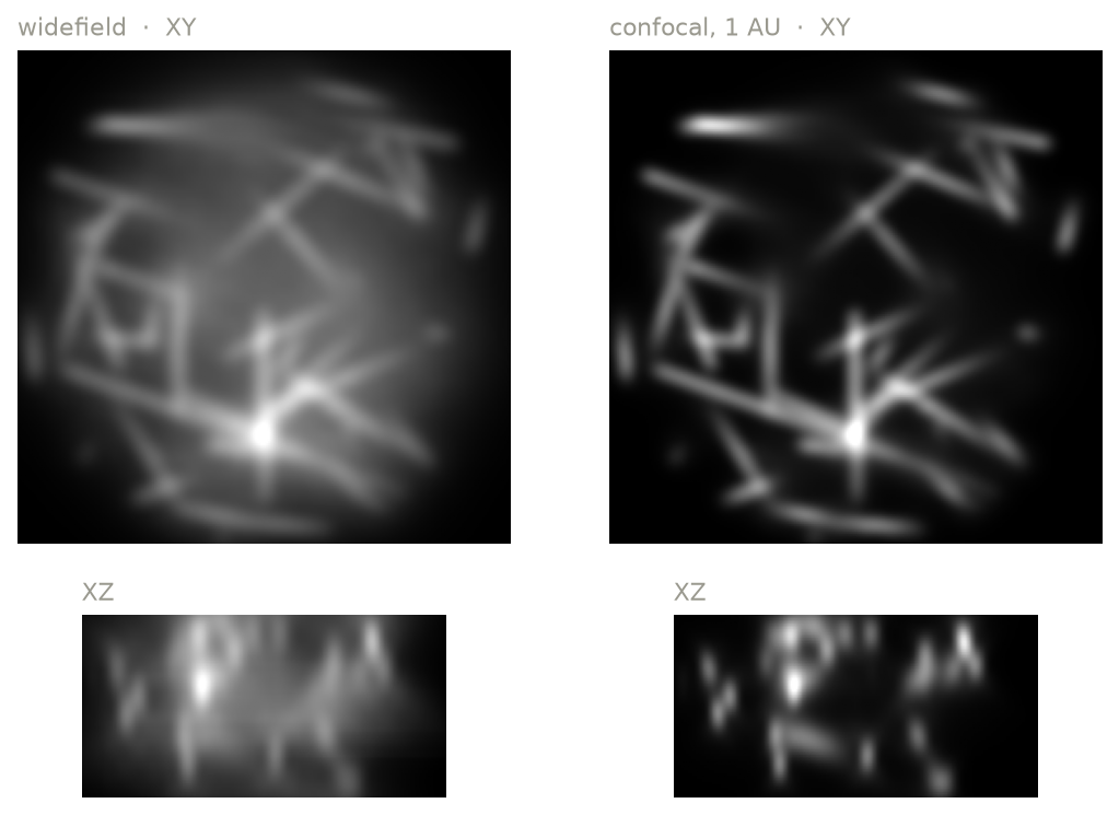
The optical image of the same random lines in widefield and in confocal with a 1 AU pinhole (XY plane through the middle of the volume, and an XZ section). This is the noise-free optical image, in the truth space: before binning to the output pixels, and before the detector. The confocal removes most of the out-of-focus light.
Widefield
The whole field is illuminated uniformly and imaged onto a camera. Each fluorophore's emission is convolved with the emission PSF. Every plane of the PSF sums to about 1: a defocused point source spreads its light over more pixels, but the total light recorded from it is the same at any focus.
Confocal
A focused laser spot is scanned across the sample, and the emission passes a pinhole before reaching a point detector. The confocal PSF is the product of
- the excitation PSF: the relative irradiance of the focused spot, 1 at the center, and
- the effective detection PSF: the emission PSF convolved with the pinhole, which is the fraction of collected light that passes the pinhole for an emitter at each position.
where \(P\) is the pinhole, a disk of diameter pinhole_au, and \(\ast\) is a
2D convolution in each plane. \(\text{PSF}_\text{ex}\) is 1 at the focus,
and \(\text{PSF}_\text{em}\) sums to 1 in each plane, so the confocal PSF at
the focus is the fraction of the collected light that passes the pinhole.
pinhole_au is the pinhole diameter in Airy units, where 1 AU is
1.22 λ / NA, measured in the sample. Smaller pinholes reject more
out-of-focus light and slightly improve resolution, at the cost of signal.
The pinhole has one physical size for all the light that passes it, so λ is one wavelength per pinhole, not the wavelength of each fluorophore:
- By default, λ is the center of the channel's emission filter passband (e.g.
525 nm for a 525/50 filter). As on many point scanners, the channels of a
track are detected
through one pinhole, and λ is the average of their band centers. With
shared_pinhole=False, each channel has its own pinhole, matched to its own band. - If a channel sharing the pinhole has no band-limited emission filter (e.g. only a longpass), λ is the mean wavelength of the emission detected in all the channels sharing it, and microsim warns.
airy_unit_wavelength_nmsets λ directly.
The excitation spot is computed at the excitation wavelengths. With several
lasers, or a broadband source, the light each fluorophore absorbs is grouped
into bands at most excitation_bin_width_nm wide
(Settings), and the spot is the sum of the
spots at each band's wavelength, weighted by the light absorbed in it.
For a point-scanning modality:
poweron the channel is the peak irradiance at the center of the spot (often kW/cm² or more), not an average over the field.exposure_msis the pixel dwell time (often 0.0005–0.01 ms), and is not divided among pixels. Channels acquired together (in one track) must have the same dwell time.- Saturation is applied at each position of the excitation spot rather than to the emission rate.
- Downsampling to the output space averages rather than sums (Spaces).
- Point-scanning microscopes record with a point detector (PMT or HyD), but microsim accepts any detector.
Widefield and confocal PSFs computed by microsim at 1.4 NA, 525 nm emission and 488 nm excitation, each scaled to its own peak. With show the signal lost at the pinhole, the confocal PSF is instead scaled by the fraction of the collected light that passes the pinhole, so it dims as the pinhole closes. Signal from a thin plane: the light recorded from a thin, uniform fluorescent layer at each distance from the focus. In widefield it is the same at every depth, so out-of-focus planes contribute as much as the focal plane; the pinhole removes it, more so the smaller it is. Smaller pinholes also narrow the PSF, mostly below 1 AU, while passing less light.
Identity
Identity applies no PSF. Use it when the ground
truth is already a microscope image (for example, a real widefield image) and
you are interested in the spectral and detector parts of the simulation:
fluorophores, filters, bleedthrough, and noise: modality=ms.Identity(), or
{"type": "identity"}.
Objective lens
ObjectiveLens sets the numerical aperture
and the refractive indices used by the PSF model. The default is a 1.4 NA oil
immersion objective.
ms.Simulation(
    ...,
    objective_lens=ms.ObjectiveLens(
        numerical_aperture=1.2,
        immersion_medium_ri=1.333,
        immersion_medium_ri_spec=1.333,
        specimen_ri=1.333,
    ),
)
| Parameter | Default | Meaning |
|---|---|---|
numerical_aperture |
1.4 | NA; cannot exceed the immersion refractive index |
immersion_medium_ri |
1.515 | refractive index of the immersion medium |
specimen_ri |
1.47 | refractive index of the sample |
coverslip_ri |
1.515 | refractive index of the coverslip |
coverslip_thickness_um |
170 | coverslip thickness |
*_spec versions |
same | the values the objective was designed for |
working_distance_um |
150 | design working distance |
The *_spec parameters describe the conditions the objective is corrected
for. When the actual values differ (a coverslip of the wrong thickness, or
the wrong immersion oil), the PSF shows the resulting spherical aberration.
The NA also sets the collection efficiency (the fraction of emitted light that enters the objective), so a lower NA gives a dimmer image as well as a larger PSF.
The PSF model
PSFs are computed with a vectorial model of a high-NA objective that
includes the Gibson–Lanni optical path difference for mismatched
coverslip, immersion, and specimen refractive indices
(microsim.psf).
The same PSF is used for the whole volume (it is spatially invariant), and is computed for a point source at the coverslip surface. Aberrations that grow with imaging depth into a mismatched specimen are therefore not included.
Emission spectrum and the PSF
The PSF depends on wavelength, and a fluorophore emits over a range of wavelengths. By default, microsim computes one PSF per fluorophore and channel, at the centroid wavelength of the detected emission. For a more accurate result, it can split the detected emission into several wavelength bins and sum one PSF per bin, weighted by the photons in that bin:
This takes proportionally longer. See Settings.
PSF caching
PSFs are cached in memory and on disk, keyed by every parameter that affects them, so repeating a simulation with a different sample, or with a detector with the same QE, does not recompute them. (The QE changes the spectrum of the detected light, and so the wavelengths at which the PSFs are computed.) See Settings.